Date of Birth

Project Overview
For this project, we had to design a circuit to display our date of birth on a seven-segment display. We had to use at least one NAND or NOR circuit and we had to use a common cathode seven segment display. We also had to use current limiting resistors. We used truth tables and K-maps to create our circuit in multisim, then used our circuit created in multisim to bread-board our design.
Truth Table
This is the truth table created for my circuit. It shows which inputs (X, Y and Z) need to be on to display the certain letters that display the number. My date of birth is November 17th, 1999. The truth table displays this date.

|

This shows which letter corresponds to which line. When that letter is on (1), that line will light up.
|
We used three inputs (X, Y, and Z) and seven outputs (a-g) in the truth table. The letters a-g light up when that certain letter is on. Each letter stands for a certain line in the seven segment display. When a group of these letters light up, it displays a number. We used the variable X in our truth table because we did not include the dashes in our date of birth. When it comes to K-mapping, the X's will be used as "don't care conditions."
K-Maps and Simplified Logic
|
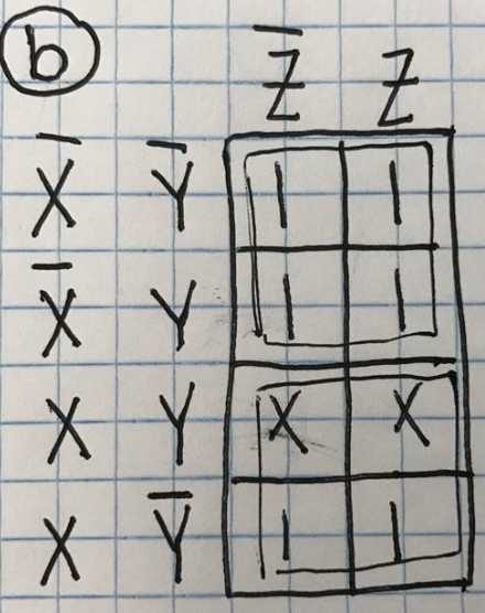
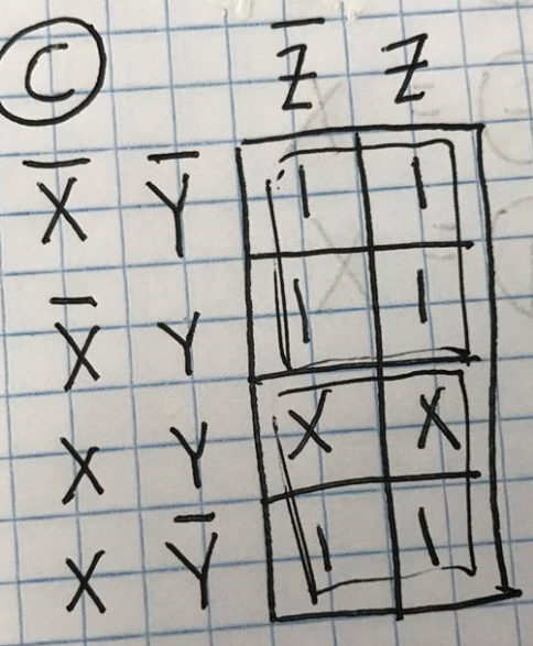
K-mapping was used to come up with my logic expressions for my circuit. When the variable X is used in K-mapping, it is used as a "don't care condition." This means you can use X as either a one or a zero. If it can help you group a big group, you can use it as a one. If it is just extra and not used in a group, it can be seen as a zero. To label the table, you put the first two inputs on the left side of the table and the next one or two inputs on the top of the table. You have to have every combination of the variables when labeling the table. You fill in each table going down each column in the big truth table. The exception is you have to switch the last two rows. When grouping, you find the biggest group to eliminate more variables making it less complicated. My expressions are very simple and the longer ones are in Sum of Products form. To find the expressions, you take the variables used in the groups. This is an easy way to arrive at your expressions which can tend to be easier than Boolean algebra. There are many expressions because there is one expression for each letter (a-g).
|

This shows how you record the numbers from the truth table in the K-maps. You switch the last two rows.
|

a=X+YZ
|
b=1
|
c=1 OR c=b
|

d=0
|

e=0
|

f=x
|

g=x OR f=g
|
Multisim
This is my circuit created using multisim. I used a common cathode seven segment display and NAND gates. The circuit is displaying my first number in my date of birth.
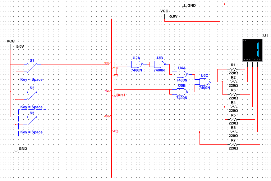
My circuit is in bus form to make the circuit more organized and less confusing. My circuit only required 5 NAND chips, which really could be 3 NAND chips because two of them can cancel out (U3B and U4A). I only needed 1 NAND chip to create my circuit because the 2 NAND gates cancel out leaving only 3 NAND gates. There are 4 NAND gates for every NAND chip. I did not have a reason to use NAND over NOR. I just picked one because we needed to use one of them. We use NAND and NOR gates so we only have to use one type of chip instead of different kinds. This saves the number of chips and the types of chips. Using the NAND chips required only one chip because the two cancel out. If I used AOI chips, I would have to use two chips because one would have to be an AND chip and one would have to be an OR chip. Using the NAND chip saved the amount of chips used and only required one kind. This would save money in producing the product. We used common cathode for this project because it is easier to understand that if it is connected to power, it is on. Common cathodes need to be connected to ground while common anodes need to be connected to power. The resistors before the seven segment display reduce the current going through the circuit. This keeps the LED lights from burning out.
Bill of Materials
This table shows the components you need for bread-boarding and how many of each component are needed. Without the right amount of materials, you can not accomplish the final product. Many wires were required along with the certain chip for it to work and of course the breadboard and seven segment display are needed. My circuit was very simple in the materials needed because I only needed one chip and not too many wires as I would have needed if it were more complicated.
Date of Birth Circuit Bill of Materials

Bread-boarding

Before: This was taken before bread-boarding. Just the NAND chip is on the board.
|
During: This was taken while working on the project. Many more wires are needed.

|

After: This is a picture of the finished product. The circuit ended up working.
|
My second bread-boarding experience was just as enjoyable as my first. My circuit ended up being very simple only requiring one NAND chip. I got mine to work on the first try which I was very excited about. I learned many new skills since this was the first time using the NAND chip while bread-boarding. Many of my letters just needed to be powered or off so it was not too difficult. The only trouble I faced was with the NAND chip. I tried three different ones because I would have to hold down the chip for it to work. This was a minor error in my circuit that was easily fixed. My second bread-boarding experience turned out just as successful as my first.
Conclusion
Overall, I liked this project very much and enjoyed working on it. It could have been because my date of birth made creating it very simple, but it was very enjoyable. I thought it was very cool how the correct numbers would show up on the seven segment display when I was done breadboarding. I learned lots about seven segments displays and the use of the common cathode instead of common anode. I would not do anything differently next time because my project turned out very successful. K-mapping is useful because you can produce the logic expressions in a fast and efficient way. I prefer doing this instead of using Boolean algebra because it is less complicated. Using the NAND chip was the most efficient way in creating my circuit for my date of birth. My project ended up working very well.
Extra Credit

This is a picture of my circuit simplified by canceling out two of the gates. I tried all the combinations of AOI, NAND, and NOR gates and the NAND gates worked best (which was the way I had it). The only segment I needed gates for was a so this was the only segment I had to check with all the different types of gates. The picture below shows the NOR and AOI gates with my circuit. None of the NOR gates cancel out, so you end up needing two chips for it. You need two different types of gates for the AOI, so you need two different chips as well. The NAND only needs one chip because two of the gates cancel out. The NAND gates/chips are the most efficient way to display this circuit and save money.