DMV Display

Project Overview
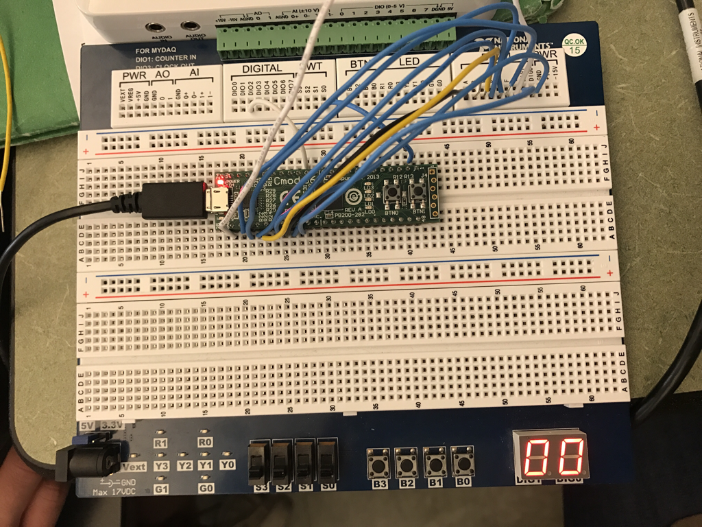
The goal for this project was to create a digital counter that displays the count from 00 to 80. The counter should have two inputs ( Next and Reset) and two outputs. The first one should count from 0-8 and the second one should count from 0-9. The design is used for employees at the DMV to known when they have served 80 customers. Once they serve 80 customers, the next employee hits the reset button and starts to serve 80 customers.
MultiSim Circuit

PLD Circuit

PLD mode is used when designing a circuit to be implemented on a PLD once you have exported directly to the chip being used. Design mode has no way of being uploaded, so it has the ability of showing you all capabilites opposed to limited capabilities of PLD. One of the tools you can use in design mode and not in PLD mode is the seven segment displays. When you are in PLD mode, you can decide what pins are used or unused and decide which ones are the inputs and outputs. There are many different pins on the chip that you can assign to a certain input or output. When you use a pin as an output, it is outputting a value at a certain time and this output can be connected to display something. Inputs are ready to detect an output and draw that signal in order to put it to use. You connect the number you picked for the inputs and outputs to that corresponding number on the board with wires. To upload, you have to push transfer and go to the ramp clock and turn it on to see the results on the board.
Bill of Materials

Conclusions
I have used two different types of integrated circuits: Medium- Scale Integration (MSI) and Small- Scale Integration (SSI). SSI chips have few gates (less than 10) and the circuits are usually more spread out and require more chips because each chip has few gates. MSI chips have more gates (10-100), but cannot be set to a lower limit so that is why we use SSI. In this project, we used both. We created the ones place using MSI and created the 10s place using SSI. This demonstrated to us how we can use the advantages of both to achieve one goal. In both we use asynchronous counters which all are affected by the "ripple effect". The ripple effect occurs because each is not connected to the same clock so a very small delay will build up bringing the counters out of synchronization. On the board, I connected each letter segment (A-G) to the corresponding output that was assigned. The clock was assigned to pin 14 so on the board I connected DIO2 to pin 14. For the switch, I connected S0 to pin 2. Lastly, I connected DIG0 and DIG1 to the corresponding pin 33 and 34. This helps display the numbers when it cycles through. Some of my classmates built their design differently with the flip-flops using inverters, but overall they were very similar. I was very happy with my end result of the project, even though I had some problems along the way.