Majority Vote

Project Overview
For this project, we had to create a circuit that would be used as a voting machine for the board of directors to eliminate controversy. To build the circuit, we could only use two input gates which made some parts of it very complicated. If there was a majority in agreement, the final vote was yes. In the case of a tie, the presidents vote was used as a tiebreaker. This report will show the votes by the members that make the final decision yes.
Problem Conception

The picture above shows the un-simplified expression. It shows when the members votes result in a yes as the decision. The expression is in Sum of Products form (SOP). To find the midterms shown above for the expression, I wrote down each combination that made the final decision yes (D=1). The SOP form is much simpler to figure out from the truth table than a POS form is.
|
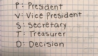
The truth table to the right shows what the members need to vote in order for the decision to be yes. The presidents vote is used in the case of a tiebreaker (if two vote no and two vote yes). The only time the presidents vote will not be considered is when the other three members have the majority vote. The number of rows has to deal with the number of variables. The number of rows is 2 to the root of the number of variables. There are 4 variables in the truth table (P, V, S, and T) so the number of rows is 16 (2^4).
|

|
Un-Simplified Circuit

The un-simplified circuit above is created by using the midterms from the un-simplified expression that I came up with from the truth table. The four inputs are shown to the left as P, V, S, and T. I used 4 inverter gates (74LS04D), 24 AND gates (74LS08D), and 7 OR gates (74LS32D). There are lots of AND gates because the AND gates can only have 2 inputs which makes it very complicated and confusing. For the chips, you would need 1 inverter chip, 6 AND chips, and 2 OR chips. There is 1 inverter chip for every 6 inverter gates. There is 1 AND chip for every 4 AND gates. There is 1 OR chip for every 4 OR gates.
Boolean Algebra

To simplify the expression, I used Boolean Algebra making it less complicated. There were many letters you could pull out to start off with to simplify the expression. I used the laws and theorems on the equation sheet to simplify. The end simplified equation ended up being: VST+PV+PT+PS which is much simpler than the other expression.
Simplified Circuit
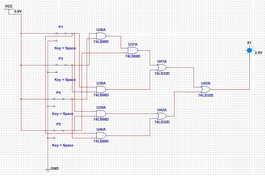
The simplified circuit above is created by using the simplified expression from the Boolean algebra. The four inputs are also shown to the left as P, V, S, and T (even though they are not labeled). I used 5 AND gates and 3 OR gates. For the chips, I used 2 AND chips and 1 OR chip. Like I said before, there is 1 AND chip for every 4 AND gates and 1 OR chip for every 4 OR gates. Also like the un-simplified circuit, we had to use the gates with 2 inputs.
The simplified circuit as you can tell saves lots of time and money because of the complexity and number of chips and wires. The simplified circuit contained 19 less AND gates and 4 less OR gates. The simplified circuit also did not have any inverter gates while the un-simplified circuit contained 4 inverter gates. Since we do not need as many gates for the simplified circuit, we do not need as many chips as well. The simplified circuit contained 4 less AND chips and 1 less OR chip. You also did not need any inverter chips while the un-simplified circuit needed 1 inverter chip. This is very important because it is a waste of money and time to create the un-simplified circuit when you can just create the simplified circuit which has the same outcome as the un-simplified version.
The simplified circuit as you can tell saves lots of time and money because of the complexity and number of chips and wires. The simplified circuit contained 19 less AND gates and 4 less OR gates. The simplified circuit also did not have any inverter gates while the un-simplified circuit contained 4 inverter gates. Since we do not need as many gates for the simplified circuit, we do not need as many chips as well. The simplified circuit contained 4 less AND chips and 1 less OR chip. You also did not need any inverter chips while the un-simplified circuit needed 1 inverter chip. This is very important because it is a waste of money and time to create the un-simplified circuit when you can just create the simplified circuit which has the same outcome as the un-simplified version.
Bill of Materials
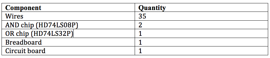
This table shows the components you need for bread-boarding and how many of each component are needed. Without the right amount of materials, you can not accomplish the final product. Many wires were required along with the certain chips for it to work and of course the breadboard and circuit board are needed.
Majority Vote Circuit Bill of Materials
Bread-boarding

Before: This is the picture of what the breadboard looks like with just the three chips.
|

During: This is the picture taken while I was working on the project, but not quite the end.
|
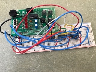
After: This is the picture taken of my final project with all the wires connected.
|
My first bread-boarding experience was enjoyable but stressful. I started on this part of the project late because I missed a day of class so when I needed a long wire, I had to cut my own since all the other ones were used up. This took away lots of time from working on the project. I learned many new things from doing this part of the project. A mistake I made is pictured in my "during" picture above. I forgot to bridge the two parts in S1 because there were many wires that had to be connected to S1. This was the only mistake I made and I found it before I got it checked. My first time getting it checked I got it right which was a success.
Conclusion
At the start of this project, it seemed like A LOT of work reading the procedure of what to do. It did end of being lots of work but it was not as hard as I thought it would be. The task for the project was to create a circuit that could be used as a voting machine for the board of directors. The first thing to do was make the truth table and come up with the logic expression. In the truth table, the zeros counted for that member saying "no" and the ones counted for that member saying "yes". The president would be used as a tiebreaker if it came down to a tie. The expression ended up being a very long expression and very confusing when it came to building in multism. The expression was long because of all the variables used for making the final decision (P, V, S, and T). Building in multisim took me many times to get it right but I finally figured it out and got it to work. The Boolean algebra also included many steps but I found this part to be somewhat easier than the others. After the long process, I came up with the simplified expression which then made the circuit in multisim much easier to create. For bread-boarding, we used the simplified expression to create the circuit. Without Boolean algebra, I could not even imagine how confusing and complex the bread-boarding for the un-simplified expression would be. This was the process of going from a problem statement to a finished circuit design. The most important thing I am taking away from this project is how much Boolean algebra helps make the expression and circuit simpler. It shows how important it is for us to learn and understand Boolean algebra to make things less complicated. Along with making things less complicated, it is important for saving money when building these circuits. The un-simplified circuit would cost much more money to build than the simplified one did. Overall, I did not think this project was too bad and I thought it turned out to be pretty successful.